Air Quality Control Systems Engineered for Your Fuels and Processes
SCR, SNCR, DSI, baghouses, wet scrubbers, and multi-pollutant control trains - engineered for your fuel, combustion system, and permit requirements.
TECHNOLOGIES
Emission Control Systems
From single-technology additions to complete multi-pollutant control trains designed as integrated systems.
Selective catalytic reduction (SCR) and selective non-catalytic reduction (SNCR) systems reduce nitrogen oxide (NOx) emissions by injecting a reagent into the flue gas stream. In an SCR system, ammonia or urea is injected upstream of a catalyst bed, where NOx reacts with the reagent to form nitrogen and water at temperatures typically between 600 and 750 degrees Fahrenheit. SNCR operates without a catalyst, injecting reagent directly into the furnace at higher temperatures (1,600 to 1,900°F) where the thermal reaction window exists. System selection depends on NOx reduction targets, ash constituents, available temperature windows, and space constraints.
Scope of supply
- SCR reactor sizing and catalyst selection
- SNCR injection grid layout and nozzle placement
- Ammonia or urea reagent storage and handling
- Ammonia injection grid (AIG) design
- DCS integration and reagent flow control
- Temperature mapping and injection zone optimization
- Catalyst life management and replacement planning
- Ammonia vaporizer system (electric or waste heat)
- Urea to ammonia thermal decomposer available
- Online cleaning for SCRs for ash-laden flue gas
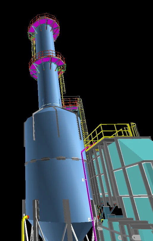
Wet scrubbers remove acid gases and particulate matter by direct contact between flue gas and a liquid reagent, typically a water-based alkaline solution. In a packed tower scrubber, gas flows upward through structured or random packing media while reagent flows downward, providing large surface area for mass transfer. Venturi scrubbers accelerate gas through a converging throat section where liquid is atomized, capturing fine particles through inertial impaction. Both configurations produce a saturated exhaust gas and a liquid waste stream that must be managed as part of the overall system design.
Scope of supply
- Packed tower and venturi scrubber design, with integrated stack and testing platform
- Reagent preparation and feed systems
- Mist elimination system
- Recirculation pump and piping system
- Wastewater handling and treatment integration
- Corrosion-resistant materials selection
- Particulate and acid gas removal performance modeling
- Ash/water separation system
- Structural steel design per local requirements (wind, seismic, snow, soil conditions, etc.)
Dry sorbent injection (DSI) pneumatically injects powdered reagents such as trona, sodium bicarbonate, or hydrated lime into the flue gas duct, where they react with and neutralize acid gases including sulfur dioxide (SO2), sulfur trioxide (SO3), and hydrogen chloride (HCl). The reacted sorbent and captured pollutants are removed together with fly ash at the downstream particulate collector, making DSI well suited to biomass and waste-to-energy plants firing high-sulfur or high-chlorine fuels. DSI operates across a broad temperature window: sodium-based sorbents (trona, sodium bicarbonate) thermally activate and are effective from roughly 300 to 600°F (150 to 315°C), while calcium-based hydrated lime extends from duct temperatures up to furnace sorbent injection above 1,500°F (815°C). Removal performance depends on sorbent selection, injection temperature, and reagent-to-acid-gas molar ratio, allowing operators to meet stringent emissions limits without the capital footprint of a wet or spray-dry scrubber.
Scope of supply
- Baseline determination of acid gas constituents and concentrations
- Sorbet retention time based on system arrangement
- Selection of sorbent (Na- or Ca- based) and delivery methods available
- Sorbent bulk receival and storage systems (with milling if necessary)
- Silo dust collection system
- Precision dosing/metering system
- Pneumatic transport system with discharge cooling/dehumidification
- Sorbent injection lances/nozzles - integrated to existing ductwork
Activated carbon injection (ACI) pneumatically injects powdered activated carbon into the flue gas stream ahead of a particulate control device (fabric filter or ESP), where it adsorbs mercury, dioxins, and furans. The carbon-bound pollutants are captured with fly ash at the downstream collector, making ACI well suited to biomass and waste-to-energy plants firing fuels high in mercury, chlorine, and trace organics. ACI is a cold-end process, since mercury adsorption is exothermic and capture efficiency improves as the flue gas cools, so injection is located where duct temperatures fall below roughly 300 to 350°F (150 to 175°C). Capture performance depends on sorbent selection and dosing rate, with halogenated (brominated) carbons enhancing mercury removal and helping operators meet stringent emissions limits without major boiler-island modifications.
Scope of supply
- Baseline determination of constituents to be treated (Hg, dioxins, furans)
- Activated carbon retention time based on system arrangement
- Selection/specification of activated carbon (i.e. halogenated) and delivery methods available
- Activated carbon bulk receival and storage systems (with milling if necessary)
- Mercury, dioxins, furans, lead, arsenic, cadmium reduction modeling - stoichiometry and mechanical design requirements
- Silo dust collection system
- Precision dosing/metering system
- Pneumatic transport system
- Activated carbon injection lances/nozzles - integrated to existing ductwork
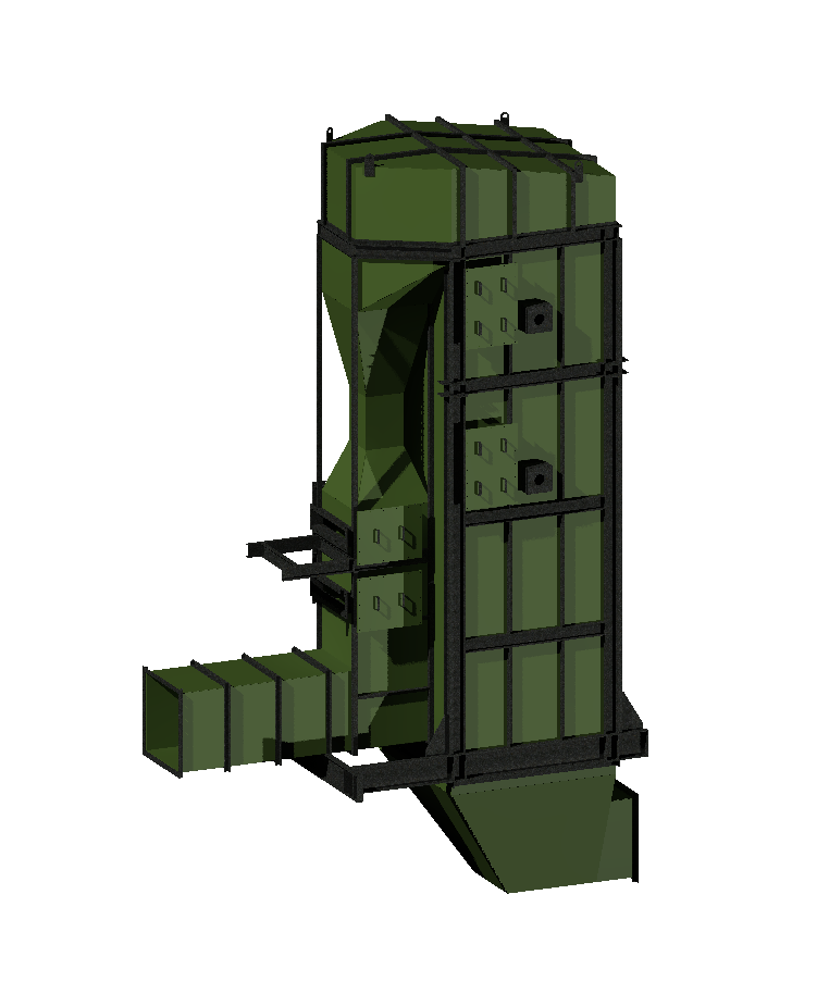
Baghouses capture particulate matter by passing flue gas through an array of fabric filter bags. As dust-laden gas enters the baghouse, particles collect on the bag surface while clean gas passes through. The accumulated dust cake is periodically removed by pulse-jet bursts of compressed air or reverse-air flow, dropping collected material into a hopper for disposal. Bag fabric, air-to-cloth ratio, and cleaning frequency are selected based on the gas temperature, particle size distribution, and required particulate emission limit. Pulse-jet baghouses are the most widely used configuration for industrial particulate control.
Scope of supply
- Pulse-jet and reverse-air baghouse with low air-to-cloth ratio
- Fabric and cage material selection for temperature, chemistry, and abrasion resistance
- Baghouse aspect ratio, bag length, velocity, and pressure drop analyses
- Casing design in consideration of the maximum positive and negative static pressures, and rate of change
- Hopper geometry and fly ash conveyance systems
- Bag cleaning philosophy (on- or offline, pulse jet, or reverse air flow) determination
- Structural steel design per local requirements (wind, seismic, snow, soil conditions, etc.)
- Modular or panelized designs
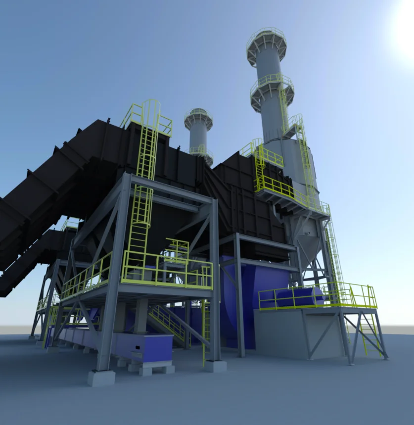
A multi-pollutant control train combines several air pollution control technologies in series to address particulate matter, NOx, CO, SOx, H2SO4, HCl, heavy metals, dioxins/furans, and other pollutants within a single integrated system. The sequence and spacing of equipment, ductwork routing between components, and overall system pressure drop determine both capital cost and long-term operating performance. Each technology in the train is designed with consideration for upstream and downstream interactions, including gas temperature changes, reagent carryover, and particulate loading effects on downstream collectors.
Scope of supply
- Process design to maximize emissions reduction and the system's thermal efficiency
- For new construction or retrofit of existing systems
- Existing fired-system heat transfer and pressure drop calculations - baseline
- Induced draft (ID) fan sizing review and recommendations
- Existing ash handling system review with recommendations (for increased fly ash volumes)
- Gas temperature profile management through heat recovery equipment by-pass control
- Integrated automation system for the train, with operator training
- Structural steel design per local requirements (wind, seismic, snow, soil conditions, etc.)
- Thermal expansion and stress analyses between new and existing equipment - minimize loads and stresses
Selective catalytic reduction (SCR) and selective non-catalytic reduction (SNCR) systems reduce nitrogen oxide (NOx) emissions by injecting a reagent into the flue gas stream. In an SCR system, ammonia or urea is injected upstream of a catalyst bed, where NOx reacts with the reagent to form nitrogen and water at temperatures typically between 600 and 750 degrees Fahrenheit. SNCR operates without a catalyst, injecting reagent directly into the furnace at higher temperatures (1,600 to 1,900°F) where the thermal reaction window exists. System selection depends on NOx reduction targets, ash constituents, available temperature windows, and space constraints.
Scope of supply
- SCR reactor sizing and catalyst selection
- SNCR injection grid layout and nozzle placement
- Ammonia or urea reagent storage and handling
- Ammonia injection grid (AIG) design
- DCS integration and reagent flow control
- Temperature mapping and injection zone optimization
- Catalyst life management and replacement planning
- Ammonia vaporizer system (electric or waste heat)
- Urea to ammonia thermal decomposer available
- Online cleaning for SCRs for ash-laden flue gas
Wet scrubbers remove acid gases and particulate matter by direct contact between flue gas and a liquid reagent, typically a water-based alkaline solution. In a packed tower scrubber, gas flows upward through structured or random packing media while reagent flows downward, providing large surface area for mass transfer. Venturi scrubbers accelerate gas through a converging throat section where liquid is atomized, capturing fine particles through inertial impaction. Both configurations produce a saturated exhaust gas and a liquid waste stream that must be managed as part of the overall system design.
Scope of supply
- Packed tower and venturi scrubber design, with integrated stack and testing platform
- Reagent preparation and feed systems
- Mist elimination system
- Recirculation pump and piping system
- Wastewater handling and treatment integration
- Corrosion-resistant materials selection
- Particulate and acid gas removal performance modeling
- Ash/water separation system
- Structural steel design per local requirements (wind, seismic, snow, soil conditions, etc.)
Dry sorbent injection (DSI) pneumatically injects powdered reagents such as trona, sodium bicarbonate, or hydrated lime into the flue gas duct, where they react with and neutralize acid gases including sulfur dioxide (SO2), sulfur trioxide (SO3), and hydrogen chloride (HCl). The reacted sorbent and captured pollutants are removed together with fly ash at the downstream particulate collector, making DSI well suited to biomass and waste-to-energy plants firing high-sulfur or high-chlorine fuels. DSI operates across a broad temperature window: sodium-based sorbents (trona, sodium bicarbonate) thermally activate and are effective from roughly 300 to 600°F (150 to 315°C), while calcium-based hydrated lime extends from duct temperatures up to furnace sorbent injection above 1,500°F (815°C). Removal performance depends on sorbent selection, injection temperature, and reagent-to-acid-gas molar ratio, allowing operators to meet stringent emissions limits without the capital footprint of a wet or spray-dry scrubber.
Scope of supply
- Baseline determination of acid gas constituents and concentrations
- Sorbet retention time based on system arrangement
- Selection of sorbent (Na- or Ca- based) and delivery methods available
- Sorbent bulk receival and storage systems (with milling if necessary)
- Silo dust collection system
- Precision dosing/metering system
- Pneumatic transport system with discharge cooling/dehumidification
- Sorbent injection lances/nozzles - integrated to existing ductwork
Activated carbon injection (ACI) pneumatically injects powdered activated carbon into the flue gas stream ahead of a particulate control device (fabric filter or ESP), where it adsorbs mercury, dioxins, and furans. The carbon-bound pollutants are captured with fly ash at the downstream collector, making ACI well suited to biomass and waste-to-energy plants firing fuels high in mercury, chlorine, and trace organics. ACI is a cold-end process, since mercury adsorption is exothermic and capture efficiency improves as the flue gas cools, so injection is located where duct temperatures fall below roughly 300 to 350°F (150 to 175°C). Capture performance depends on sorbent selection and dosing rate, with halogenated (brominated) carbons enhancing mercury removal and helping operators meet stringent emissions limits without major boiler-island modifications.
Scope of supply
- Baseline determination of constituents to be treated (Hg, dioxins, furans)
- Activated carbon retention time based on system arrangement
- Selection/specification of activated carbon (i.e. halogenated) and delivery methods available
- Activated carbon bulk receival and storage systems (with milling if necessary)
- Mercury, dioxins, furans, lead, arsenic, cadmium reduction modeling - stoichiometry and mechanical design requirements
- Silo dust collection system
- Precision dosing/metering system
- Pneumatic transport system
- Activated carbon injection lances/nozzles - integrated to existing ductwork
Baghouses capture particulate matter by passing flue gas through an array of fabric filter bags. As dust-laden gas enters the baghouse, particles collect on the bag surface while clean gas passes through. The accumulated dust cake is periodically removed by pulse-jet bursts of compressed air or reverse-air flow, dropping collected material into a hopper for disposal. Bag fabric, air-to-cloth ratio, and cleaning frequency are selected based on the gas temperature, particle size distribution, and required particulate emission limit. Pulse-jet baghouses are the most widely used configuration for industrial particulate control.
Scope of supply
- Pulse-jet and reverse-air baghouse with low air-to-cloth ratio
- Fabric and cage material selection for temperature, chemistry, and abrasion resistance
- Baghouse aspect ratio, bag length, velocity, and pressure drop analyses
- Casing design in consideration of the maximum positive and negative static pressures, and rate of change
- Hopper geometry and fly ash conveyance systems
- Bag cleaning philosophy (on- or offline, pulse jet, or reverse air flow) determination
- Structural steel design per local requirements (wind, seismic, snow, soil conditions, etc.)
- Modular or panelized designs
A multi-pollutant control train combines several air pollution control technologies in series to address particulate matter, NOx, CO, SOx, H2SO4, HCl, heavy metals, dioxins/furans, and other pollutants within a single integrated system. The sequence and spacing of equipment, ductwork routing between components, and overall system pressure drop determine both capital cost and long-term operating performance. Each technology in the train is designed with consideration for upstream and downstream interactions, including gas temperature changes, reagent carryover, and particulate loading effects on downstream collectors.
Scope of supply
- Process design to maximize emissions reduction and the system's thermal efficiency
- For new construction or retrofit of existing systems
- Existing fired-system heat transfer and pressure drop calculations - baseline
- Induced draft (ID) fan sizing review and recommendations
- Existing ash handling system review with recommendations (for increased fly ash volumes)
- Gas temperature profile management through heat recovery equipment by-pass control
- Integrated automation system for the train, with operator training
- Structural steel design per local requirements (wind, seismic, snow, soil conditions, etc.)
- Thermal expansion and stress analyses between new and existing equipment - minimize loads and stresses
PROJECT EXAMPLES
Emissions control engineering
project examples
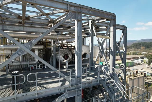
THE CPE DIFFERENCE
Engineers who understand
the combustion and heat transfer upstream
CPE has been designing air pollution control systems since the firm’s founding - alongside boilers and combustion systems. That means APC equipment is sized from actual combustion modeling and fuel analysis, not just a flue gas data sheet.
Design depth across APC technologies
CPE’s engineers have developed technologies for baghouses, SCR, SNCR, DSI, ACI, and wet scrubber systems based on boiler OEM experience. That design-level understanding shows up in every project, whether it is a new system, a retrofit, or a vendor evaluation.
Multi-discipline delivery
Process, mechanical, structural, electrical, and controls under one roof. No inter-firm coordination gaps between the emissions control technology designer and the foundation engineer.
Scan-to-design for retrofits
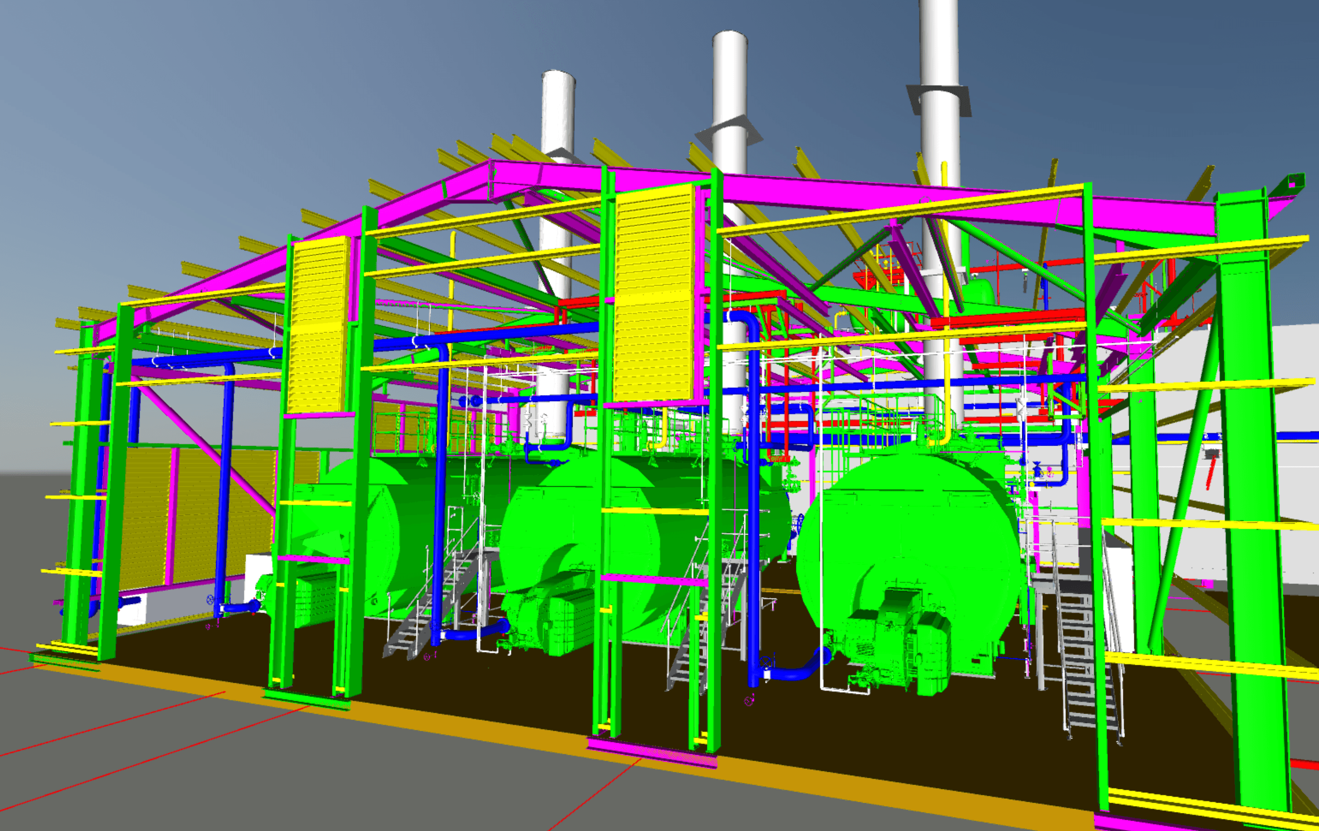
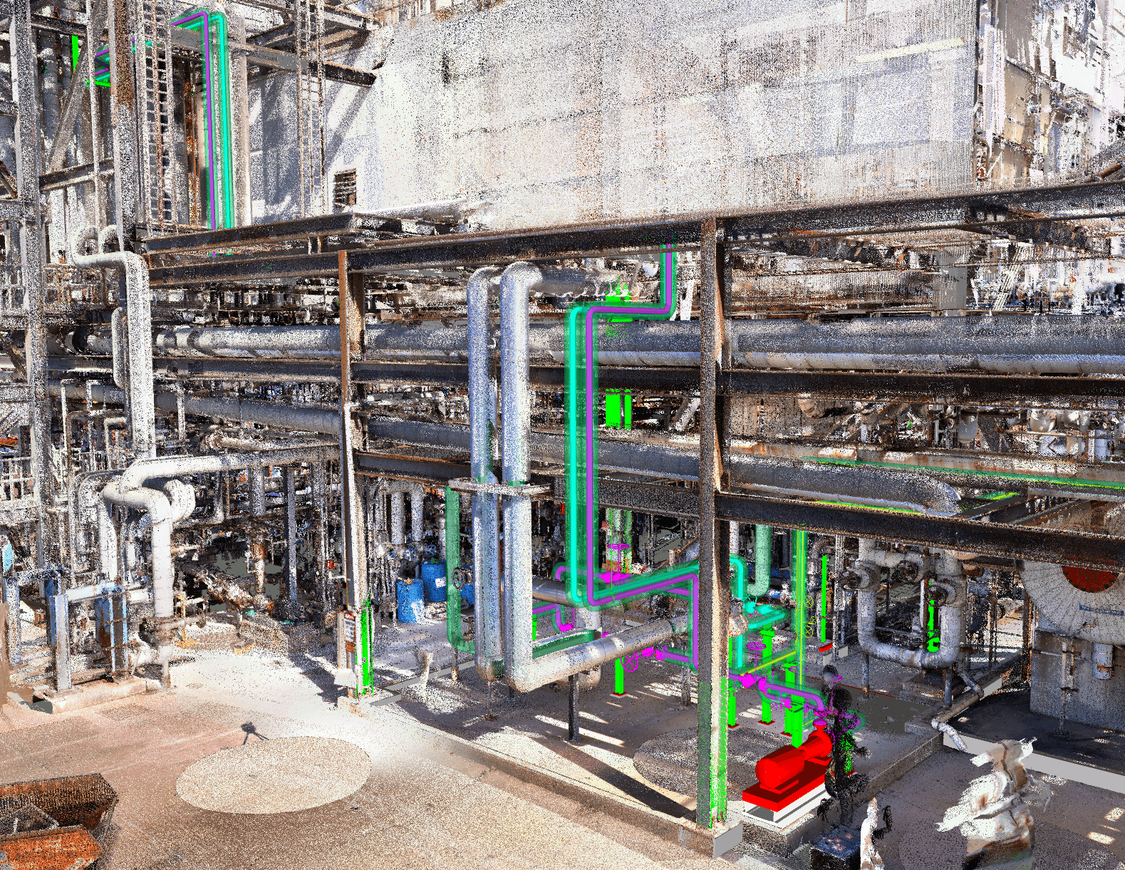
In-house laser scanning captures existing plant conditions so new APC equipment can be designed to fit tight spaces around active operations.
Fabrication through startup
From equipment specifications and shop inspection through installation observation and emissions testing, CPE stays involved past the drawing set.
Have an emissions control
application question?
Tell us about your compliance challenge or APC project and we will let you know how CPE can help.
OUR SERVICES
Engineering Depth Across the Project Lifecycle
From initial assessment through construction-ready deliverables - boilers, combustion systems, steam and condensate, emissions control, and energy infrastructure.