Solid Fuel Combustion Systems
Combustion technology selected based on fuel, emissions, and operating conditions - Stoker (multiple types), BFB, and CFB with combustion air and fuel distribution
TECHNOLOGIES
Solid Fuel Combustion Systems
Full spectrum of challenging service, solid fuel combustion technologies, selected based on fuel, emissions, and operating conditions.
A technology selection study evaluates candidate combustion systems against a project's specific fuel properties, emissions requirements, and operating conditions. Performance modeling generates a techno-economic comparison that accounts for capital cost, operating cost, fuel flexibility, and emissions compliance. For existing boilers or third-party OEM equipment, the evaluation incorporates furnace geometry and available combustor height as governing constraints that narrow the field of viable technologies.
Scope of supply
- Performance modeling of fuel properties and emissions profiles
- Techno-economic comparison of candidate combustion technologies
- Operating condition analysis and load range evaluation
- Furnace geometry and combustor height constraint assessment
- Retrofit feasibility studies for existing boiler installations
- Third-party OEM equipment evaluation and integration review
Stoker systems burn solid fuel on a mechanical grate at the base of a furnace, delivering primary air from below and overfire air from above to control heat release and emissions. Grate type, sizing, and undergrate air zone configuration are tailored to the fuel's moisture content, particle size distribution, and ash characteristics. All moving grate components are designed using dynamic endurance limit modeling to ensure long-term mechanical reliability under challenging thermal conditions.
Scope of supply
- Traveling grate design and sizing
- Vibrating grate configurations (air- and water-cooled)
- Pinhole inclined grate configurations (water-cooled)
- Reciprocating grate configurations (air-cooled)
- Undergrate air zone configuration tailored to fuel characteristics
- Retrofit packages, OEM-furnished systems, and integrated boiler packages
- Endurance limit modeling for all moving components and their connections
A bubbling fluidized bed combustor suspends fuel and inert bed material on an upward stream of air bubbles, creating a turbulent, well-mixed combustion zone in the lower furnace. The open-bottom, modular design allows bubble cap and sparge pipe layouts to be optimized for specific bed material, fuel ash properties, bed depth, and operating conditions. Fuel feed point locations are selected to ensure uniform distribution across the bed, and the transport disengaging height is sized to limit carryover of bed material and unburned fuel.
Scope of supply
- Open-bottom, modular BFB combustor design
- Bubble cap and sparge pipe layout optimization
- Bed depth and material particle size distribution selection
- Transport disengaging height (TDH) analysis
- Fuel feed point quantity and location determination
- Bed feed, handling, and recycle system design
- Bubble cap design optimized for bed material and fuel ash properties
- Bed turndown & temperature control design
- Bed chemistry design (sulfur capture or agglomeration reduction)
A circulating fluidized bed operates at higher air velocities than a BFB, carrying solids upward through the furnace and into a cyclone separator where they are collected and returned to the combustion zone. This continuous solids loop produces relatively uniform temperatures, longer reaction times, and inherently lower emissions (than BFB or stoker). Cyclone separator sizing, loop seal configuration, and solids recirculation rate are optimized around ash particle size distribution, fuel fixed carbon, and particle attrition to maintain stable bed inventory and consistent heat release.
Scope of supply
- Cyclone separator sizing and quantity (refractory or water-cooled)
- Loop seal configuration and solids recirculation optimization
- Refractory lining specification for high-temperature and -wear
- Fuel ash chemistry and particle attrition analysis
- Furnace wall falling-particles analysis - abrasion resistance design
- Furnace heat release analysis - in-furnace heat transfer surface design (wing-wall evaporators or superheaters)
- In-bed sulfur capture design (limestone injection)
- Bed material extraction and cooling system design
- Fuel feed type and locations determined by fuels and the system's operating load profiles
Fuel metering and distribution systems deliver solid fuel to the combustion zone at controlled rates and in a uniform spatial pattern. Feed equipment type, sizing, number of feed points, and feed wall configuration are determined by the combustion technology, furnace geometry, and the physical & chemical characteristics of the fuel. Proper metering stabilizes and reduces the emissions profile, prevents agglomeration/clinkering, reduces unburned carbon, and enables stable load following across the operating range.
Scope of supply
- Fuels classification study and analysis (PSD, bulk density - packed and loose, moisture content range, ash content range, flowability assessment)
- Analysis of system operating and load change profiles - number and type of fuel feed points
- Design of the fuel distribution equipment with in-furnace helper systems (pneumatic, mechanical, or gravity)
- Multiple fuel metering system design types (live bottom screw, hydraulic pusher)
- Integration with stoker, BFB, and CFB combustion systems
- Load-following capability across the full operating range
- Fuel metering bin feed design (variable rate or overflow type designs)
Combustion air systems deliver undergrate/UGA (primary), overfire/OFA (secondary) to the furnace in controlled splits. Undergrate ductwork layout, air distribution modeling, windbox arrangement, and OFA nozzle sizing collectively determine combustion efficiency, carbon burnout, and emissions performance. Multiple proprietary OFA nozzle designs are available, each selected based on furnace geometry, fuel type, and the specific emissions targets of the installation.
Scope of supply
- OFA systems design for new-build and retrofits
- Proprietary OFA nozzle designs (from simple to complex, depending on application)
- Undergrate air zoning and control to improve efficiency and emissions
- Detailed boiler or fired-equipment performance model informs each design
- Evaluate benefits of flue gas recirculation for NOx reduction applications
- Fans selection, damper sizing, and pressure drop analysis
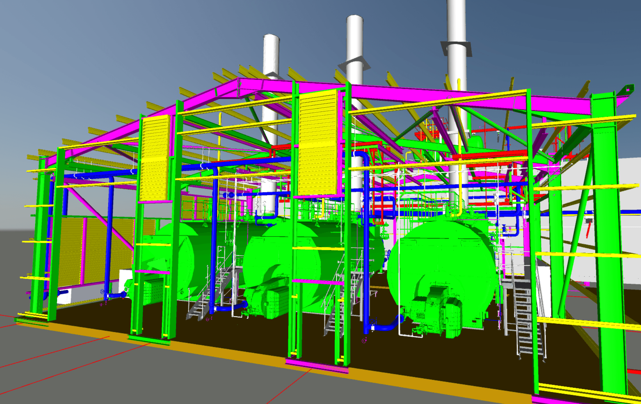
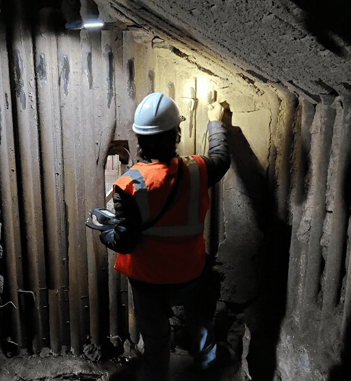
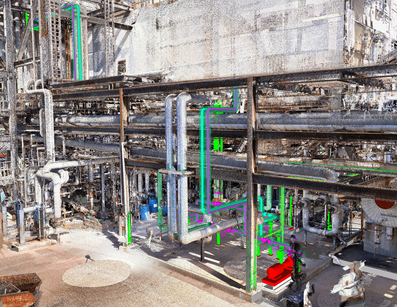
- Integrated system design with 3D laser scanning and modeling
- Combustion air heater design
- Combustion control sequence updated with operator training
Bottom ash and bed material handling systems remove solids from the lower furnace and cool and transport it for recycle or disposal. System configuration varies by combustion technology: stoker installations use drag chain or screw conveyors at the grate discharge, while fluidized bed systems require bed drain and recycle circuits to maintain proper bed inventory. Ash chute/hopper geometry, conveyor sizing, and cooling equipment are selected based on ash volume, temperature, and abrasion characteristics.
Scope of supply
- Bottom ash handling for stoker, BFB, and CFB systems
- Ash chute or hopper configuration and sizing
- Submerged ash drag and screw conveyors for stokers
- Hollow flight screw conveyor for CFB combustors
- Air-cooled vibrating sifting conveyors for BFBs
Refractory systems protect structural components in high-temperature combustion environments. Design philosophy favors minimizing refractory content in favor of membrane wall construction, which improves heat transfer and reduces maintenance. Where refractory is required, material selection, lining thickness, and attachment details are engineered for temperature profile and excursions, environment (oxidizing or reducing), flue gas chemistry, and mechanical loads. Thermal expansion management and wear protection address erosion- and corrosion-prone zones.
Scope of supply
- Heat flow calculations to determine required thermal resistance to achieve skin temperatures
- Materials options analysis for available space, anchor requirements, weight of liner, heat flow, abrasion resistance, chemical resistance, heat-up curves, expected life of liner, installation & maintenance costs
- Structural deflection analysis
- Thermal expansion analysis (enclosure skin, refractory liner, refractory anchors)
- Refractory installation and expansion joint detail drawings
- Refractory anchor and attachment detail drawings
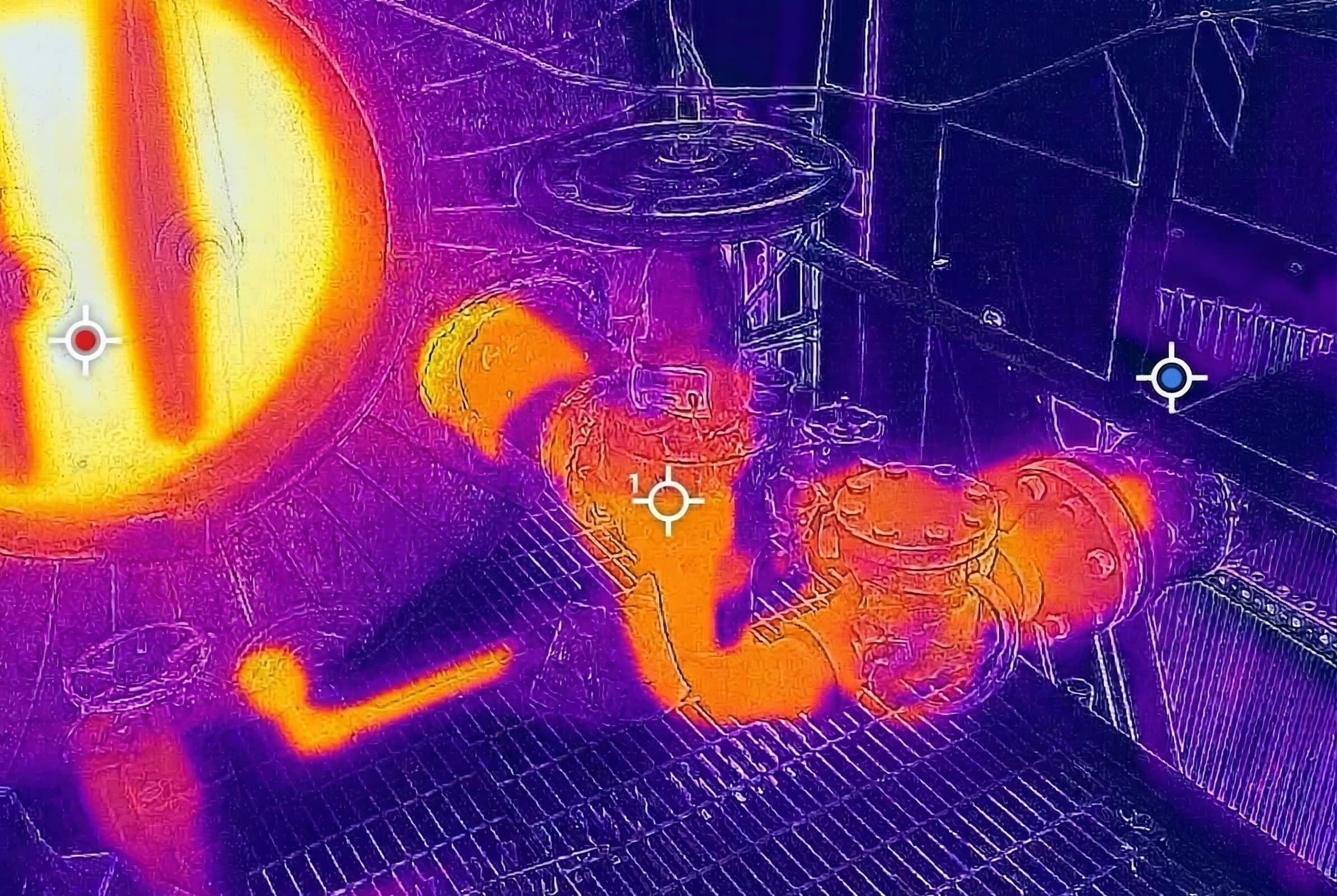
Combustion controls and instrumentation monitor and regulate the entire combustion process, from fuel feed and air delivery through emissions output. Flame detection, combustion air flow measurement, bed temperature monitoring, and fuel feed interlocks work together to maintain safe, efficient operation. Burner management system (BMS) and combustion controls logic are designed to comply with NFPA 85/86 and applicable safety standards, providing automated protection against unsafe operating conditions.
Scope of supply
- Flame detection and combustion monitoring
- Combustion air flow measurement and control
- Bed temperature monitoring systems
- Fuel feed interlocks and safety logic
- Burner management system (BMS) and combustion control logic design
- Compliance with NFPA 85/86 and applicable safety standards
- Oxygen trim & emissions biasing controls
- Development of empirical operating solutions that allow operators to select a condition and the system adjusts to presets (i.e. high vs. low moisture, summer vs. winter, highly variable load vs. stable load, etc.)
PROJECT EXAMPLES
Combustion engineering
project examples
Power Boilers
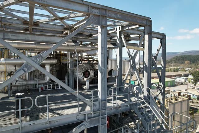
BFB boiler for high-moisture biomass - South America
Complete BFB boiler design for a biomass facility in South America, handling high-moisture fuels with custom combustion and heat transfer engineering.
Debottlenecking
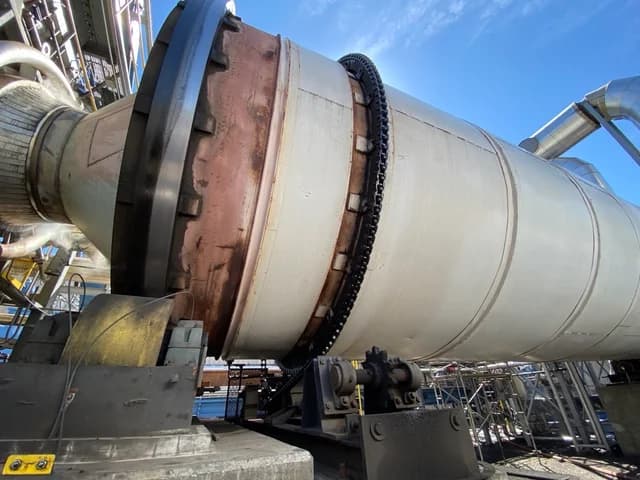
Biochar Facility Debottlenecking & Capacity Expansion
A comprehensive pyrolysis yield analysis with heat and mass balance to identify process and equipment constraints and engineer a path for tripling biochar production capacity.
Energy Audits
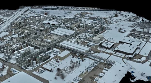
Comprehensive Energy Audit Identifies Major Fuel-Savings Opportunities at a Specialty Chemicals Plant
CPE evaluated interconnected boiler, steam, condensate, and waste heat systems at a specialty chemicals facility, identifying 17 MMBtu/hr in potential natural gas savings and developing actionable strategies for thermal-efficiency and GHG-reduction projects.
THE CPE DIFFERENCE
Combustion is where
CPE started
CPE was founded on combustion and steam generation engineering. The team designs, troubleshoots, and tunes the systems they engineer - closing the loop between design assumptions and field performance.
Core technology expertise
Combustion is CPE's founding discipline. The team designs furnaces, grate systems, BFB combustors, air systems, and fuel feed - not as add-ons, but as the primary practice.
Custom performance models
Proprietary heat and mass balance tools and CFD modeling calibrated to real operating data across stoker, BFB, CFB, and gas/oil-fired systems.
Fuel flexibility engineering
Design and retrofit experience across biomass, bagasse, RDF, coal, natural gas, hydrogen-blends, and fuel oils - including multi-fuel and fuel conversion projects.
Field tuning and commissioning
CPE engineers tune the systems they design. On-site combustion optimization, flue gas analysis, and performance benchmarking close the loop between design and operation.
Have a combustion
question?
Tell us about your boiler or combustion system and we will let you know how CPE can help.
OUR SERVICES
Engineering Depth Across the Project Lifecycle
From initial assessment through construction-ready deliverables - boilers, combustion systems, steam and condensate, emissions control, and energy infrastructure.